Case B
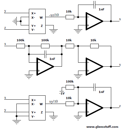

I do not wish to plagiarize the work of another, but an appropriately brief repeat of what has already been written will suffice for introductory purposes here. The systems in question are all three-dimensional and are algebraically simpler than the famous Lorenz and Rössler systems, which were for some time considered to be the simplest examples of autonomous dissipative systems of ordinary differential equations with chaotic solutions.
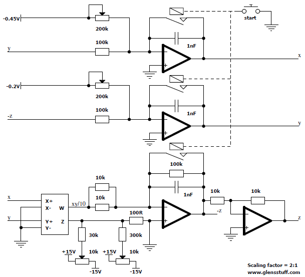
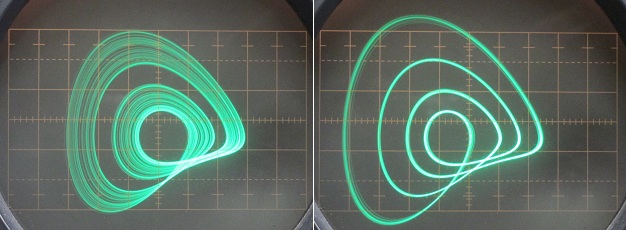
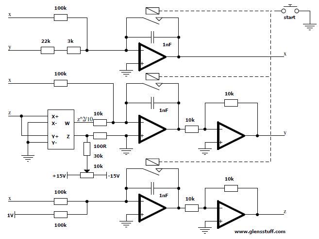
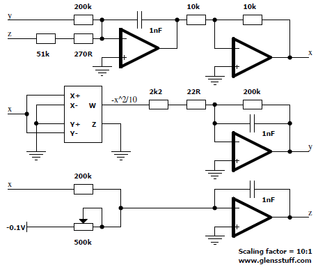
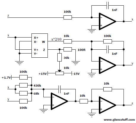
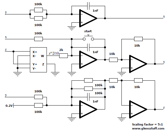
Each system electrical analogue was constructed on solder-less breadboard after idealized verification in SPICE. For each system a simplified schematic diagram of the circuit is provided, along with oscilloscope screen photos of various 2-dimensional plane views. For each system I also produced a video of a 3-dimensional projective view, showing continuous rotation about a single axis. In the case of all videos the y axis is plotted vertically and the seemingly alive, chaotic object on display rotates in the x-z plane about the y axis pointed vertically.
My inspiration for the production of these videos comes from Sprott's own GIF animations. These displays were produced with the aid of my my three-dimensional projective unit, with a temporary modification to the microcontroller firmware. I modified the code such that the front panel potentiometers are ignored and instead the angle of rotation about the x axis remains fixed while the angle of rotation about the y axis continuously rotates zero through 360 degrees at a fixed and steady rate.
This endeavour is just an exercise in translating and scaling systems of differential equations into electrical analogues. While the equations are quite simple and only a few actually needed to be scaled, it is still an exercise not completely without worth because this kind of stuff doesn’t become second nature without some degree of rote repetition. Well, OK, there’s all of that and of course the fact that it is actually quite satisfying to see these complex, animated systems come alive on the oscilloscope screen after plugging in all of the wires.
In all cases the multiplier(s) used are AD633 and the op-amps are AD711.


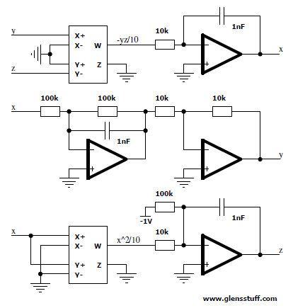

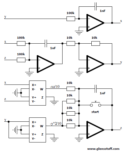

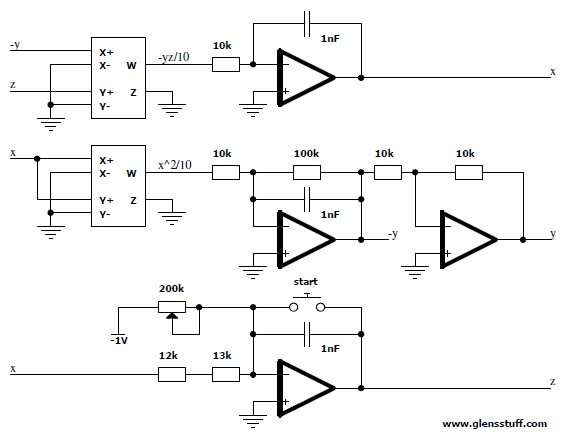
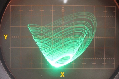
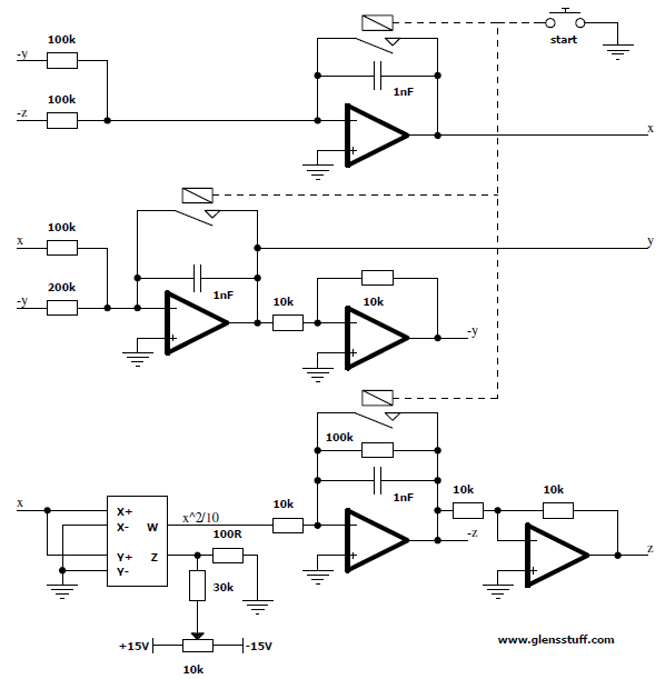

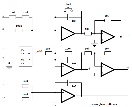

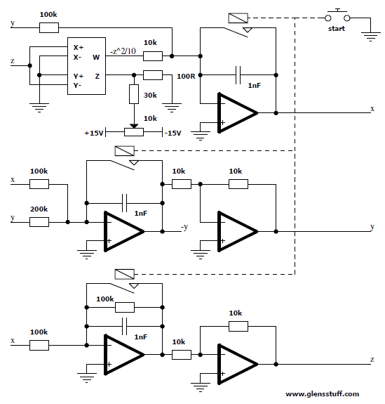

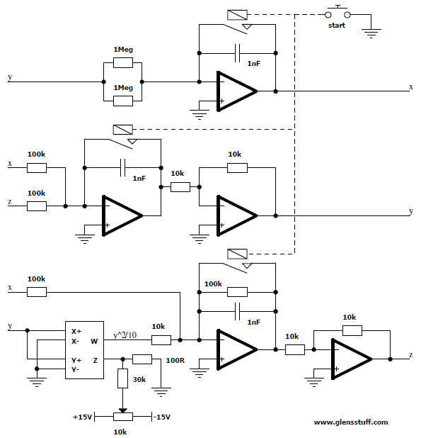
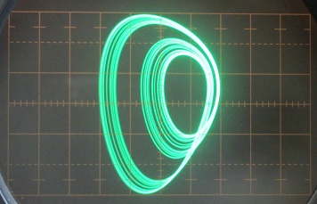
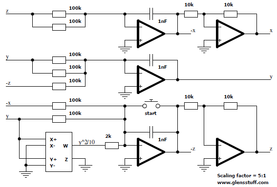

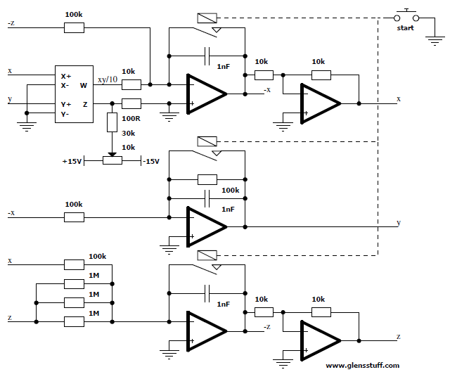

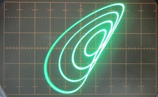



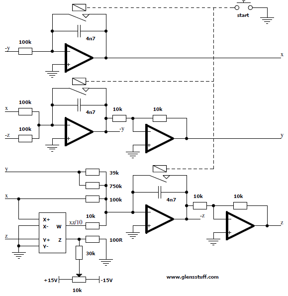

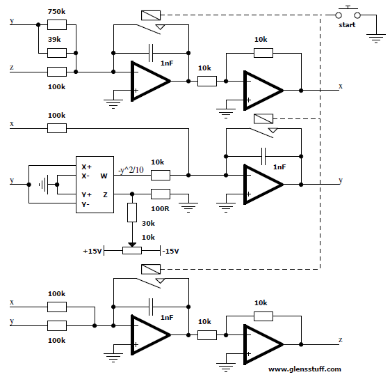

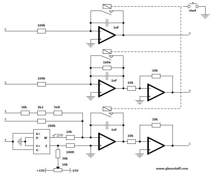

Error announcement: I got a sign the wrong way around in this analogue. This escaped my attention because the constructed system still remained valid, producing an attractor very similar to that of the correct System Q. See my Self-Programming Analog Computer For Chaotic Sprott Systems for the correct implementation.
Thanks to Robert R. Fenichel for noticing this mistake.
