There are several other small-diameter types sporting the same type phosphor and even higher maximum acceleration potentials that would presumably work just as well at presenting a bright (if not more so) video-image raster over the entirety of their display faces as the type 2AP1A. However a 2AP1A is what I happened to have in my possession and regardless I was intrigued and motivated from then on to eventually experiment with the making of an actually functional, even if limited in practicality, composite video display unit using a 2AP1A C.R.T.

![]()
Well, all of that changed recently after I acquired several more type 2AP1A cathode-ray tubes on eBay. However this time the tubes were “N.O.S.” (“new-old-stock”), unused and still in their original, unopened packages. As it turned out, my previous example, acquired well over ten years ago, was indeed substantially worn-out and low on cathode emission.
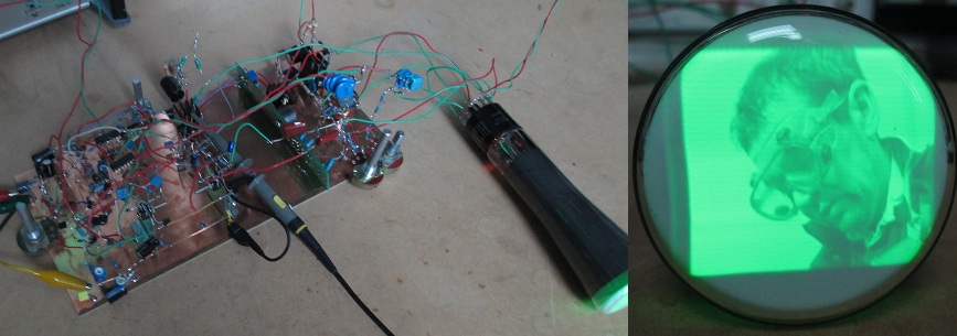
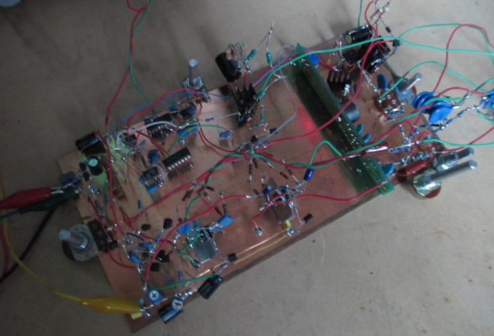
With the new tubes at hand I finally got restarted on this endeavour once again on one Saturday morning and the outcome of that weekend’s effort is detailed here. The circuitry is crude and the physical realisation on a blank sheet of P.C.B. laminate isn’t particularly pretty, but I was limited in both time and by what parts I had immediately at hand; that I could rummage from my numerous junk boxes. In any case, the prototype experimentation was a success and, to my delight, the type 2AP1A C.R.T. is indeed capable of displaying a monochrome video raster of passable brightness and image quality.
As a matter of fact I was quite surprised at the quality of the images I managed to produce, particularly in the level of detail (namely the resolution) visible on such a small (2-inch diameter) display. At the time of writing this I am working on the side on the construction of a refined video monitor version to be housed in a 3U, 19-inch relay rack case, intended to eventually act in part as a video version of a transmitter "side tone" receiver/monitor-combination for both amateur and slow-scan television transmission.
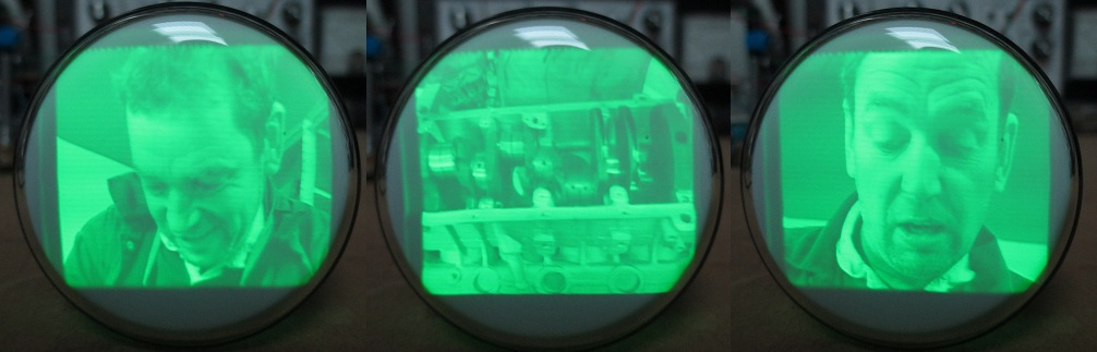
Immediately below are some screen photographs showing the quality of the immages attained. Being a bit of a petrol-head the D.V.D. player that I took into the shack from the house at the time to serve as the composite video source just happened to be loaded with A 4X4 is born, presented by British television personality Mark Evans. In hindsight (purely in my subjective opinion of course) Freema Agyman or Kate Bush (just for example) would have been a great deal more photogenic, but I just so happen to think that Doctor Who is a silly load of tosh and unfortunately I do not have any D.V.D.’s of terrible 1980’s pop music in my collection either, so Mr Evan’s mug and the Land Rover V8 will just have to do.
In addition to the four D.C. rail potentials a 6.3V 0.6A A.C. supply is required for the C.R.T. filament / heater. This was also furnished by an external bench supply (one of my Marconi model TF1109A’s also providing the +300V D.C.).
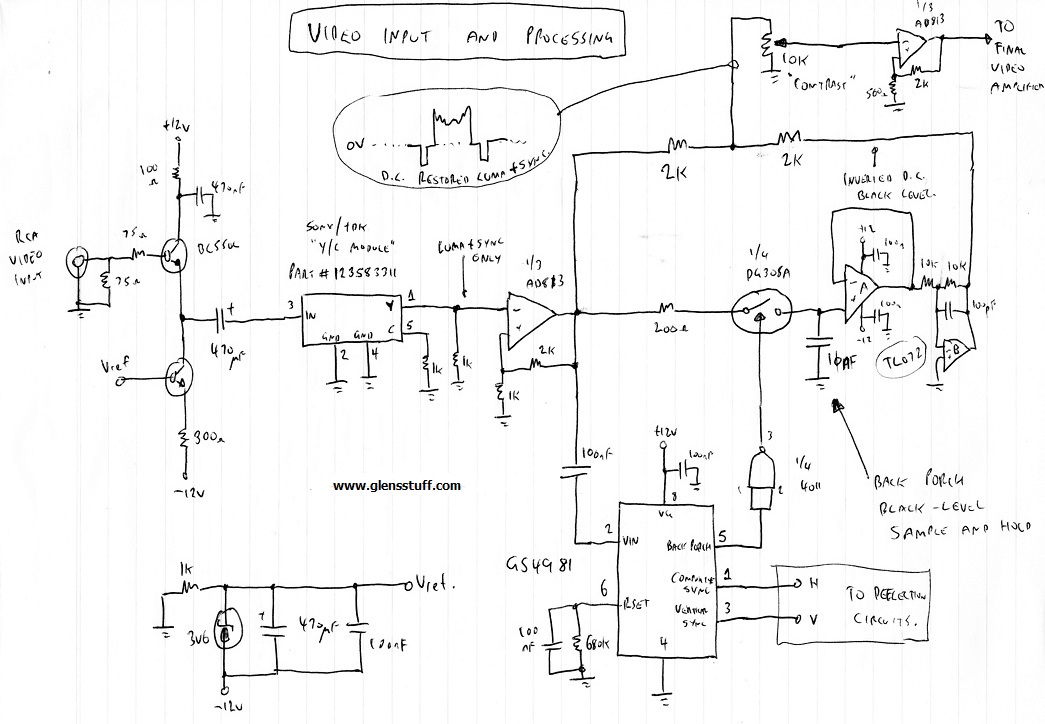
The sync is separated by the GS4981 dedicated sync-separator I.C. (essentially equivalent to the venerable National LM1881). The composite (horizontal) and vertical sync outputs from this I.C. synchronise the deflection ramp generators, but the “back porch” output is used to gate the sample-and-hold based on 1/4 of a DG308A quad analogue switch. During each back porch interval the 10nF sample-and-hold capacitor is charged towards the back porch D.C. potential. This potential is the black level and is essentially stabilised to 0V by the sample-and-hold D.C. restorer. The back porch potential developed across the 10nF capacitor is buffered and then unity-gain inverted by the TL072 JFET-input dual op-amp. The sampled back porch potential is effectively subtracted from the composite luminance and sync video signal at the junction of the two 2k resistors feeding the “contrast” control potentiometer.
D.C. restoration is mandatory for any high quality video display as without it the black-level reference of the displayed picture will not remain fixed, but instead constantly vary up and down in accordance with the average amplitude of the luminance video component. From the wiper of the contrast control potentiometer, the D.C.-restored monochrome video signal is buffered and amplified by approximately 4.6 by another third of the AD813 triple op-amp package. The third op-amp of the AD813 triple isn't used and in hindsight could have been used to buffer the input signal instead of the discrete emitter follower, but I had already assembled that part of the circuitry before rummaging through my junk boxes to find a suitable op-amp for the proceeding stage!
The next diagram details the horizontal and vertical ramp generation and high-voltage amplifiers for driving the deflection plates of the C.R.T. and thus producing a raster display.
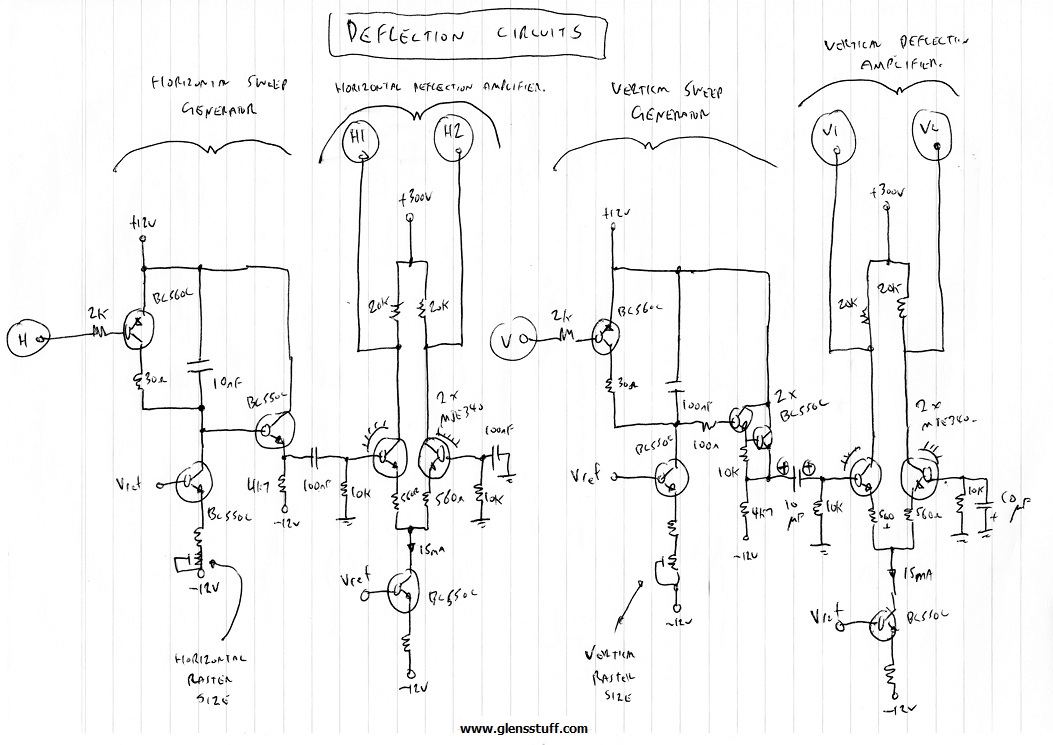
The ramp signals developed across the capacitors are buffered by emitter followers to preserve their linearity prior to being fed to the deflection plate amplifiers. As the 2AP1A C.R.T. has rather
low specified deflection sensitivities, differential deflection plate signals of several hundred volts are required to produce a raster covering the full face of the C.R.T. These deflection
signals are furnished by the MJE340-transistor differential-output signal amplifiers operating from the +300V supply rail. Oddly enough, the deflection factors for the 2AP1A are given in metric
units of volts per millimetre. Operating with a final acceleration potential of 1kV, the horizontal and vertical deflection sensitivities are 0.13mm per volt and 0.11mm per volt respectively.
This means that, in order to deflect the beam from the central position to the edge of the screen, either left or right, the potential difference between the horizontal deflection plates must be
25.4mm / 0.13mm = ~200V. Since this is only half a screen of deflection, the required differential voltage swing between the horizontal deflection plates translates to approximately 400V
peak-to-peak. The vertical deflection is a little less sensitive, requiring approximately 460Vp-p. The deflection plate amplifiers operating on the +300V supply rail furnish this differential
voltage swing with adequate operating headroom as they saturate at signal output of a little under 600Vp-p.
The final scribbled circuit diagram to be presented details the C.R.T. and video amplifier circuitry. The 2AP1A requires a final anode (acceleration) potential of 1kV, while the grid must be driven negative with respect to the cathode to control the display intensity. The more negative (with respect to the cathode) the grid potential, the lesser the brightness.
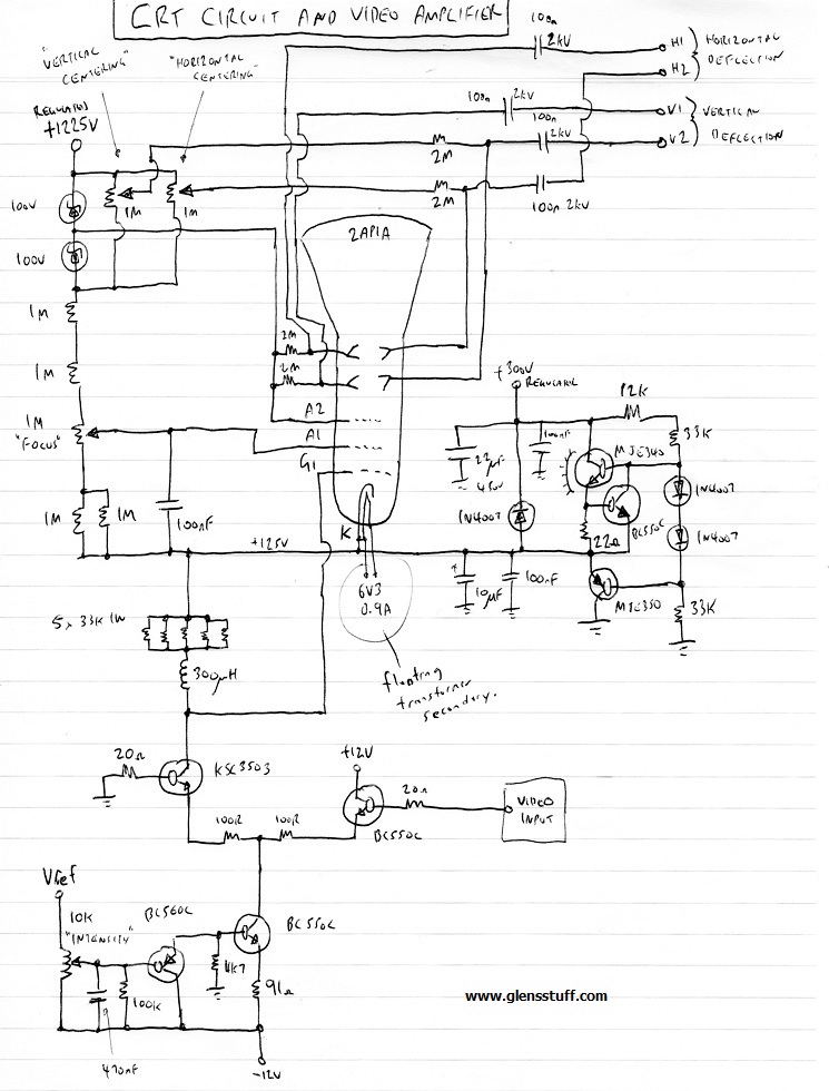
The “tail” current of the differential-pair video amplifier, and thus the quiescent D.C. operating point at the grid of the C.R.T., is controlled over a limited range by a potentiometer thus effectively serving as the display brightness or “intensity” control.
A zener diode and resistive divider string between the +1225V regulated supply rail and the +125V cathode potential furnishes the necessary D.C. potentials for the focusing control grid, final acceleration anode and the deflection plates. From the junction of the two series-connected 100V zener diodes, the final anode and one each of the vertical and horizontal deflection plate pairs are tied to the required potential of 1kV above the cathode.
Horizontal and vertical raster positioning adjustment is provided by the potentiometer pair that permits one plate of the horizontal and vertical deflection pairs to be varied +/- 100V with
respect to its partner. This provision is necessary because the manufacturing tolerances in these C.R.T.’s are rather loose and an undeflected electron bean is seldom aimed directly at the
centre of the C.R.T. face!
However, for the best possible deflection linearity, the deflection plate potentials for the centred raster should have an average potential between them equal to the final anode potential.
Ideally, this would be furnished by having, for each deflection plate pair, a dual-gang positioning potentiometer with its halves wired in anti-phase, such that the D.C. potential of one deflection
plate is adjusted either above or below the anode potential while its companion is adjusted an equal amount in the opposite direction. I did not, however, have a suitable pair of dual-gang
potentiometers immediately at hand when I built this primitive prototype, but this is one of the many circuit refinements that I have designed into the final video monitor design that I am
currently constructing.
14 March 2015